Introduction
Mining pipelines rarely run through perfectly uniform ground. A single route may cross solid rock, compacted backfill, sloping terrain, and areas where the soil continues to settle after construction. These changes can affect how the pipe is supported and may create additional stress along the pipeline.
For UHMWPE mining pipes, wear resistance and impact resistance are important when transporting abrasive materials such as mineral slurry and tailings. However, choosing a wear-resistant pipe does not eliminate the risks associated with uneven bedding, differential settlement, or poorly supported connections.
Before installation, engineers should assess the ground conditions, burial depth, pipe dimensions, joint locations, and support arrangement. Understanding how these factors interact helps reduce the risk of leakage, deformation, and unexpected maintenance in demanding mining environments.
A Pipeline Route Is Not Just a Line on a Drawing
A mining pipeline may begin on competent rock, cross a section of excavated ground, and continue through soil that was placed during site development. On a drawing, these sections may look like one continuous route. Under operating conditions, they can behave very differently.
Rock provides a different type of support from loose fill. A compacted trench behaves differently from waterlogged ground. An above-ground section supported on separate foundations introduces another set of mechanical conditions.
These differences matter because a pipe does not experience only internal pressure. It must also withstand the loads created by its own weight, the transported material, the surrounding soil, supports, connected equipment, and any movement along the route.
UHMWPE is sometimes considered for mining pipelines because of its wear resistance, impact resistance, and relatively low density. Those properties can be useful, but they do not remove the need for suitable trench preparation or support design.
When a pipeline develops a leak near a change in terrain, the first question should be whether the failure was caused by internal wear, external loading, movement, or a combination of these factors.
Why the Transition Between Two Ground Conditions Matters
Consider a buried pipe crossing from solid rock into backfilled soil. The rock section may remain relatively stable, while the fill settles as it consolidates or changes moisture content.
If the pipe follows the ground movement uniformly, the effect may be manageable. The problem arises when one section moves more than the next. This is known as differential settlement.
Differential settlement can change the pipe's curvature and create additional loads at the transition. Depending on the pipe dimensions, joints, pressure, and support conditions, these loads may lead to deformation or damage.
A similar problem can occur where a pipeline crosses a road that has been excavated and reinstated. If the backfill is not prepared as specified, the pipe may lose uniform support after the surface appears complete.
The visible failure may occur some distance away from the point where the ground first moved. For this reason, a maintenance team should examine the surrounding route rather than focusing only on the exact location of a leak.
What UHMWPE Can and Cannot Accommodate
UHMWPE has useful mechanical properties, including impact resistance and the ability to deform under certain loading conditions. However, the allowable deformation of a finished pressure pipe cannot be determined from a general material elongation value.
Tensile elongation measured in a laboratory test describes the behavior of a specimen under a defined test method. It does not establish the allowable bending strain, joint movement, or settlement tolerance of a complete pipeline.
Pipe dimensions matter. A larger outside diameter, different wall thickness, higher operating temperature, and different joint arrangement can change the system's response to external movement. Long-term loading also matters because thermoplastic materials can exhibit creep.
The design should therefore use the actual product data and the expected ground conditions. If a route is likely to experience significant settlement, the engineering team should establish the acceptable movement and determine whether the pipe, joints, and support arrangement can accommodate it.
Flexibility is a design property to be evaluated, not a reason to ignore the ground.
Buried Pipe Installation: Bedding Is Part of the Design
For buried pipelines, the surrounding soil helps support the pipe and transfer external loads. The installation method affects how that support develops.
A trench should be prepared according to the approved project specification. The bedding material should provide appropriate support and should not contain unsuitable sharp objects that could create concentrated contact loads. Backfill placement and compaction should follow the requirements for the actual installation.
A trench cut into rock may need different preparation from a trench in ordinary soil. Simply placing a pipe on an uneven rock surface can create localized loading. A transition from rock to soil may require additional attention because the stiffness of the support changes along the route.
Minimum cover should also be established for the actual loading conditions. A pipeline under a mining haul road does not face the same external loading as a line installed in a protected area without vehicle traffic.
Cover depth alone does not confirm that a pipe is adequately protected. Pipe dimensions, soil properties, compaction, traffic loads, and the manufacturer's installation requirements must be considered together.
Above-Ground Pipelines Have Their Own Settlement Risks
Above-ground pipelines avoid some buried-pipe problems, but they introduce support-related risks.
A long pipe section may be carried by several supports. If one support settles or moves, the spacing and load distribution change. The pipe may develop a longer unsupported span or experience additional bending near a fixed point.
The effect depends on pipe dimensions, operating temperature, the weight of the contents, pressure, and support geometry. Support spacing should be calculated or specified for the actual product rather than copied automatically from an existing steel pipeline.
Fixed points and guides also need to be positioned carefully. Thermoplastic pipes can expand and contract with temperature changes. If movement is restrained inappropriately, additional loads may develop at anchors, flanges, and equipment connections.
For a sloping pipeline, the design should also address axial movement and the forces transferred to supports. The appropriate arrangement depends on the route and the manufacturer's instructions.
Connections Are Often the Weakest Part of a Poorly Supported System
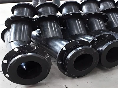
A pipe section may tolerate some movement while a flange connected to a rigid pump does not. If the pipeline shifts, the joint can become misaligned or transfer additional loads into the equipment nozzle.
During installation, workers should not force misaligned components together by tightening the bolts. The pipe and equipment should be positioned and supported correctly before the connection is assembled.
If a joint leaks after the ground settles, simply replacing the gasket may provide only temporary relief. The team should check whether the connected sections have moved and whether the support arrangement needs correction.
The same principle applies to buried transitions and above-ground supports. A reliable pipe system requires compatible movement and loading behavior across the complete route.
What Should Be Surveyed Before Construction?
A route survey should identify changes in ground conditions, slope, drainage, existing excavations, road crossings, and areas that may be affected by future mine activity.
For buried sections, record soil conditions, groundwater observations, trench requirements, cover depth, and backfill specifications. For above-ground sections, identify support foundations, support spacing, fixed points, guides, and access for inspection.
The design should show bends, joints, flanges, valves, transitions, and connections to equipment. If the route passes through an area with uncertain ground conditions, document the assumptions and identify where additional engineering review is required.
After installation, create an as-built drawing. Record actual joint locations and support positions, including any changes made during construction. When a failure occurs later, this record helps engineers compare the original design with the installed system.
Technical Data for Mining Pipe Installation
The following values are general engineering references. They do not define the allowable deformation, cover depth, or support spacing of a particular UHMWPE pipe.
|
Parameter |
Numerical reference |
Relevance |
|
Length conversion |
1 m = 1,000 mm |
Measuring settlement and pipe dimensions |
|
Route conversion |
1 km = 1,000 m |
Recording pipeline length |
|
Pressure conversion |
1 MPa = 10 bar |
Comparing design and operating pressure |
|
Gravity acceleration |
Approximately 9.81 m/s² |
Used in gravitational-load calculations |
|
UHMWPE molecular-weight classification |
Commonly above 1,000,000 g/mol |
General material identification |
|
Typical density of many unfilled UHMWPE grades |
Approximately 0.93–0.94 g/cm³ |
Material reference; verify the grade |
|
Differential settlement |
Project-specific, measured in mm or m |
Requires route and ground assessment |
|
Minimum cover |
Project-specific |
Depends on soil, traffic, and pipe design |
|
Bedding and backfill specification |
Project-specific |
Must match the installation design |
|
Pipe outside diameter |
Product-specific |
Required for external-load assessment |
|
Pipe wall thickness |
Product-specific |
Required for pressure and mechanical assessment |
|
Support spacing |
Product- and design-specific |
Depends on geometry, temperature, and loading |
|
Allowable pipe movement |
Manufacturer- and design-specific |
Must not be inferred from tensile elongation alone |
How to Investigate a Failure Near a Settlement Zone
When a pipeline fails near a ground transition, document the location before changing the installation. Record the pipe's elevation, joint position, visible deformation, and surrounding ground condition.
If the line is buried, inspect the bedding and backfill during excavation. Look for uneven support, sharp contact points, washout, or evidence that the surrounding ground has moved. If the line is above ground, check support elevations, foundation conditions, and any change in the unsupported span.
Next, compare the failure location with the route drawing and operating history. If the line has experienced pressure fluctuations or repeated abrasion, those factors should also be investigated.
The replacement specification should address the identified cause. That may involve improved trench preparation, a revised support arrangement, a different joint location, or a product change supported by engineering analysis.
Conclusion
A mining pipeline crossing different ground conditions must be designed for more than internal pressure. Differential settlement, uneven bedding, changing support conditions, and movement at rigid connections can all affect reliability.
UHMWPE may be a suitable material for some mining applications, especially where abrasion resistance is important. Its flexibility should not be treated as a substitute for route assessment, installation control, and proper support design.
A useful design begins with an accurate survey and ends with an accurate as-built record. When settlement-related failures occur, investigating the ground and support conditions can be just as important as selecting a replacement pipe.
Frequently Asked Questions
1. Can UHMWPE pipes tolerate differential settlement?
The allowable movement depends on the finished pipe, its dimensions, joints, operating conditions, and installation. Significant settlement requires engineering assessment rather than reliance on general material elongation values.
2. Why is the transition from rock to backfilled soil a concern?
The two ground conditions may provide different support stiffness. If the fill settles more than the rock, the pipe may experience additional bending or joint loads.
3. Can above-ground UHMWPE pipes use the same support spacing as steel pipes?
Not automatically. Material stiffness, temperature, pipe dimensions, contents, and support geometry should be considered when determining suitable support spacing.
4. Does a deeper burial always protect a mining pipe better?
No. Cover depth is only one part of the design. Soil conditions, compaction, traffic loading, pipe dimensions, and installation quality also affect external loads.
5. What information should be provided for a pipeline crossing unstable ground?
Provide the route and elevation drawings, soil information, expected movement, pipe dimensions, operating pressure, installation method, joint details, and the manufacturer's relevant design limits.
Request a Mining Pipe Installation Review
Luoyang Zhengju New Materials Technology Co., Ltd. supplies UHMWPE pipeline products for suitable mining applications. If your project crosses rocky ground, backfilled areas, slopes, or potential settlement zones, share the route drawings and operating conditions for a product suitability review.
Website: https://www.cnzjpipe.com/
Primary Keyword: UHMWPE mining pipe installation
Secondary Keywords: mining pipeline settlement, UHMWPE pipe support design, buried mining pipe installation, mining pipeline ground movement